- Rookie
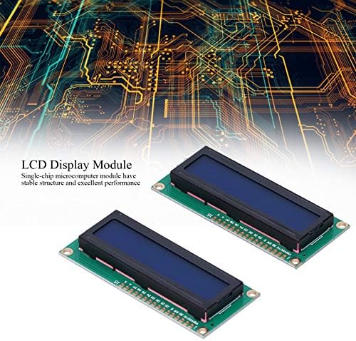
Módulo Microcomputador de Microcomputador de Chapé Filmado, Material PCB da placa de microcomputadores de único Chip para aprendizado
Existem 16 caracteres por linha, 2 linhas no total, que adotam interface paralela O produto vem com tamanho pequeno, baixo consumo de energia e operação de exibição fácil. Pode ser usado para aprender, testar, desenvolvimento, que é prático e útil. Não apenas um produto necessário para robôs com rodas, mas também o dispositivo mais direto para interface interativa. O 1602 usa uma interface padrão de 16 pinos. O módulo microcomputador de chip único possui estrutura estável e excelente desempenho. Existem 16 caracteres por linha, 2 linhas no total, que adotam interface paralela. O produto vem com tamanho pequeno, baixo consumo de energia e operação de exibição fácil. Pode ser usado para aprender, testar, desenvolvimento, que é prático e útil. Não apenas um produto necessário para robôs com rodas, mas também o dispositivo mais direto para interface interativa. O 1602 usa uma interface padrão de 16 pinos. O módulo microcomputador de chip único possui estrutura estável e excelente desempenho. Existem 16 caracteres por linha, 2 linhas no total, que adotam interface paralela2.
Folha de dados
- Item Type:
- Single-Chip Microcomputer Module
- Material:
- PCB
- Purpose:
- Learning, testing, development
- Power Supply Voltage:
- DC 5V
- Number of Characters:
- 16 characters, 2 lines
- Product Size:
- Approx. 80 x 36mm / 3.1 x 1.4in
- Screen Size:
- 65x14
- How to Use:
- Pin 1:
- VSS is the ground power
- Pin 2:
- VDD is connected to 5V positive power supply
- Pin 3:
- V0 is the contrast adjustment terminal of the liquid crystal display. The contrast is the weakest when the positive power is connected, and the contrast is the highest when the power is grounded. When the contrast is too high, it will produce ghost images. When using it, you can adjust the contrast through a 10K potentiometer
- Pin 4:
- RS is the register selection, the data register is selected when the level is high, and the instruction register is selected when the level is low
- Pin 5:
- R/W is the read and write signal line, read operation at high level, and write operation at low level. When RS and RW are both low level, the command or display address can be written. When RS is low level and RW is high level, the busy signal can be read. When RS is high level and RW is low level, data can be written
- Pin 6:
- The E terminal is the enable terminal. When the E terminal changes from high level to low level, the LCD module executes the command
- Pins 7 to 14:
- D0 to D7 are 8-bit bidirectional data lines
- Pin:


